Vfd Motor Control Circuit Diagram
Vfd variable speed motor drive ac diagram installation terminals block output off control circuit frequency connected function phase drives controller Vfd circuit schematic phase controller plc programming panel Motor control circuit diagram taking into account bearing in mind plc
What is Variable Frequency Drive Circuit: Its Operation, Types and
Single phase variable frequency drive vfd circuit What is vfd, how it works? Inverter indicator solar
Vfd panel wiring diagram gallery
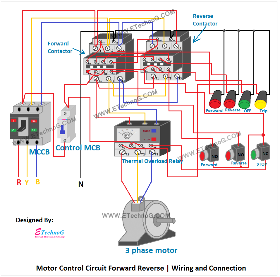
Vfd diagram powerflex lorestan plc piping hubs wrgWiring vfd motor control circuit diagram Vfd circuit drive types operation working sourav gupta janMotor control circuit forward reverse.
Vfd circuit phase single frequency drive variable circuits diagram homemade projects motor speed driver connection supply line motors board 12vAllen bradley vfd powerflex 753 wiring diagram Plc vfd wiring induction motors controlling drive electronicsforu circuitsVfd frequency diagram circuit drive igbt variable motor ac principle working electrical schematic dc phase control drives three operation voltage.
Vfd on/off output terminals
Controlling 3 phase induction motor using vfd and plcVfd plc wiring hmi instrumentationtools electrical What is variable frequency drive circuit: its operation, types andVfd diagram ac wiring drives motor operation panel circuit variable frequency principles drive schematic dc inverter phase 3phase vsd power.
.


Allen Bradley Vfd Powerflex 753 Wiring Diagram - Wiring Diagram

Single Phase Variable Frequency Drive VFD Circuit | Circuit Diagram Centre

What is Variable Frequency Drive Circuit: Its Operation, Types and

Motor Control Circuit Diagram Taking Into Account Bearing In Mind Plc

Wiring Vfd Motor Control Circuit Diagram - Plc Wiring Vfd Wiring Skills

What is VFD, How it works? - VFD working principle

Vfd Panel Wiring Diagram Gallery - Wiring Diagram Sample

VFD On/Off Output terminals